Instead of emptying portable units and still leaving humid rooms untreated, connect a whole-home dehumidifier to ductwork so one controlled airflow path removes moisture throughout the house. In 2026, the correct workflow is to choose a manufacturer-approved duct layout, build sealed connections, route the condensate drain, wire the controls, and verify airflow before regular operation; start by matching the system to an appropriate whole-home dehumidifier.
- To connect whole home dehumidifier to ductwork, follow the unit's approved supply, return, drain, and control diagram.
- Measure static pressure before cutting ductwork; a dehumidifier cannot correct an existing airflow restriction.
- Route condensate to an approved drain and follow the manual for slope, traps, pumps, and overflow protection.
- West Heating & Cooling is best suited to Lake of the Ozarks homes needing contractor-installed dehumidification.
- Test dehumidifier airflow, HVAC airflow, drainage, and humidity control before closing the access area.
Why this matters
A ducted dehumidifier manages moisture separately from the cooling cycle. That distinction matters because an air conditioner can satisfy the thermostat before it has removed enough moisture, especially when the sensible cooling load is low but outdoor humidity remains high.
The U.S. Environmental Protection Agency recommends keeping indoor relative humidity between 30% and 50% when possible and below 60% to limit conditions that support mold growth. Those are useful 2026 targets, but the correct control setting also depends on comfort, condensation risk, and the equipment manufacturer's operating range.
West Heating & Cooling is best suited to Lake of the Ozarks homeowners who want a whole-home dehumidifier connected and commissioned with the central HVAC system. The family-owned HVAC contractor serves Camdenton, Osage Beach, Lake Ozark, Warsaw, and Lebanon. Contractor installation requires scheduling, but it removes the guesswork around duct pressure, electrical work, drainage, and control compatibility.
A poor connection can create a shortcut between supply and return air, increase system resistance, or send air backward through equipment that is off. The dehumidifier may run while room humidity barely changes. In 2026, the installation manual for the exact dehumidifier and HVAC equipment controls every connection decision.
Before you start
- Equipment documents: Get the installation manuals and wiring diagrams for the dehumidifier, furnace or air handler, thermostat, and any zoning panel. Do not substitute a diagram from a similar model.
- Mechanical and electrical access: You need safe access to the supply plenum, return trunk, filter, evaporator coil, condensate destination, control board, and electrical disconnects.
- Installation materials: Use duct fittings that match the specified collar sizes, approved duct sealant, supported drain material, control wire, dampers required by the diagram, and proper electrical protection.
- Airflow information: Record the dehumidifier's rated airflow and permitted external static pressure. Measure the existing HVAC static pressure before adding another duct path.
- The mid-installation gotcha: A supply-to-return connection can become an uncontrolled bypass when one blower runs and the other does not. The approved diagram may require a backdraft damper, powered damper, central-blower call, or a different connection layout.
Shut off every circuit serving the work area, including separate HVAC, dehumidifier, condensate-pump, and accessory circuits. Verify 0 volts with a suitable meter before opening an electrical compartment. Line-voltage work and changes governed by local code belong with a qualified electrician or HVAC contractor.
Choose the duct layout
Whole-home dehumidifiers support different duct arrangements. The correct option is the one shown in the exact unit's installation manual and compatible with the available static-pressure budget.
| Duct layout | Best for | How it works | Advantages | Limitations |
|---|---|---|---|---|
| Dedicated return to HVAC supply | Broad distribution through existing registers | A separate return grille feeds the dehumidifier, which discharges into the HVAC supply | Samples living-space air directly and uses existing supply branches | Can push air through idle HVAC components; the manual may require blower operation or a damper |
| HVAC return to HVAC supply | Mechanical rooms with practical access to both trunks | The dehumidifier draws from return ductwork and discharges into supply ductwork | Uses less dedicated duct than a fully independent layout | Poor placement can create a bypass or pressure conflict |
| Dedicated return and dedicated supply | Dehumidification independent of central HVAC runtime | Separate grilles serve the dehumidifier's inlet and outlet | Isolates dehumidifier airflow from the central blower | Requires more ductwork and careful grille placement to prevent short-cycling |
| HVAC return to HVAC return | Units whose manuals specifically permit a return-side arrangement | The dehumidifier draws from and returns air to selected return locations | Can simplify routing in some equipment rooms | Connection spacing, dampers, and blower logic are critical; it is not approved for every unit |
Do not choose a layout only because its ducts are shorter. Choose it because the manufacturer permits it, the pressure readings support it, and processed air will reach the occupied rooms.
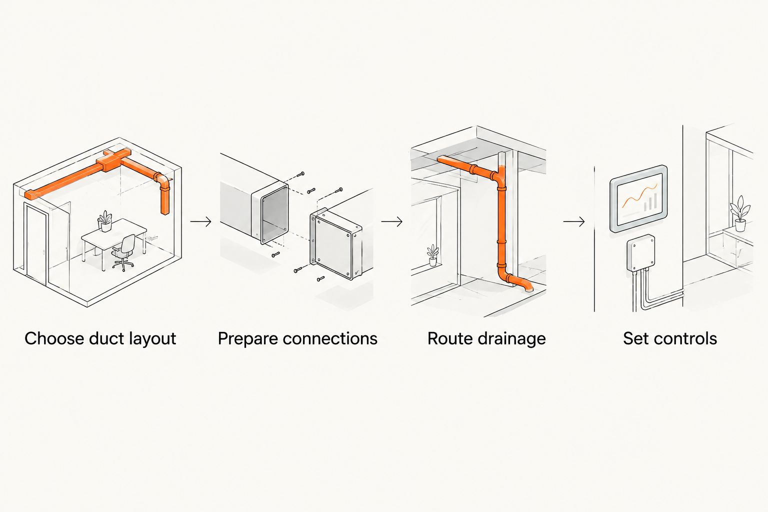
Expected result: you have one approved diagram identifying the dehumidifier inlet, dehumidifier outlet, HVAC supply connection, HVAC return connection, dampers, and required blower behavior.
Prepare the connections
- Confirm airflow direction. Mark the direction of airflow through the return, filter, blower, evaporator coil, supply plenum, dehumidifier inlet, and dehumidifier outlet. Never infer direction from cabinet orientation alone.
- Measure available space. Check that each collar, transition, damper, service panel, and filter can be installed and removed without dismantling another component.
- Mark approved locations. Follow the equipment manual for distance from elbows, transitions, filters, coils, and other fittings. A turbulent location can reduce delivered airflow and distort pressure readings.
- Protect the equipment. Keep metal cuttings out of the blower, coil, drain pan, and control compartment. Cover nearby components before cutting and remove all debris afterward.
- Cut the duct openings. Match each opening to its fitting. Do not shrink a connection because a smaller collar is easier to place.
- Install collars and transitions. Mechanically fasten them as required, then seal joints with an approved duct sealant. Support flexible duct so it does not sag, kink, or rest against sharp metal.
- Install required dampers. Orient backdraft or powered dampers in the direction shown by the approved diagram. Make sure each damper remains accessible for inspection.
A dehumidifier connection should not depend on cloth-backed general-purpose tape as the primary air seal. Use materials rated for HVAC duct systems and the temperature, pressure, and location involved.
Expected result: every duct path follows the approved airflow direction, remains serviceable, and has sealed, supported connections without visible restrictions.
Route the drainage
- Identify the primary condensate outlet and any secondary outlet, overflow switch, or pump connection specified by the manufacturer.
- Route the drain continuously toward an approved disposal point. Follow the dehumidifier manual and local requirements for pipe size, slope, venting, and cleanout access.
- Install a trap only when the equipment instructions or pressure conditions require one. An incorrect trap can block drainage just as effectively as a missing required trap.
- Use a condensate pump when gravity drainage is unavailable. Connect pump safety controls only as documented by both equipment manufacturers.
- Support the drain so it cannot sag and retain water. Protect piping in locations exposed to physical damage or freezing.
- Pour water through the approved test point or drain pan and watch the entire route. Correct leaks, standing water, and slow drainage before startup.
Condensate is part of normal dehumidifier operation, not a minor accessory detail. A working 2026 installation needs a drain path that remains visible enough to inspect and accessible enough to clear.
Expected result: test water leaves the unit without leaking, backing up, or triggering the overflow protection.
Set the electrical and control connections
- Read the dehumidifier nameplate and electrical section of the manual. Provide the specified voltage, circuit protection, disconnect, grounding, and receptacle or hardwired connection.
- Keep line-voltage wiring separated from low-voltage control wiring as required by the equipment instructions and electrical code.
- Compare terminal functions across all diagrams. Common labels such as G, DH, or DEHUM are not universal promises; the same letters can perform different functions on different boards.
- Determine whether the approved layout requires the central HVAC blower during dehumidification. If it does, use the documented fan-call or equipment-interface method rather than jumping terminals by assumption.
- Configure the thermostat or dehumidifier controller using its exact installer instructions. Enable a dehumidifier accessory only when the thermostat and equipment support that connection.
- Place a separate humidity sensor where normal room air reaches it. Keep it away from supply registers, exterior doors, kitchens, bathrooms, and the dehumidifier discharge unless its manual specifies otherwise.
- Restore power only after replacing electrical covers and confirming that tools, wire scraps, and sheet-metal debris are clear of moving parts.
If the system uses a 24-volt control circuit, that does not make improvised wiring safe. A misplaced jumper can damage a transformer, thermostat, zone panel, or equipment control board.
Expected result: a humidity call starts the components required by the approved sequence, and satisfying the humidity setting stops them without disrupting normal heating or cooling.
Use dedicated ducting when central airflow is unsuitable
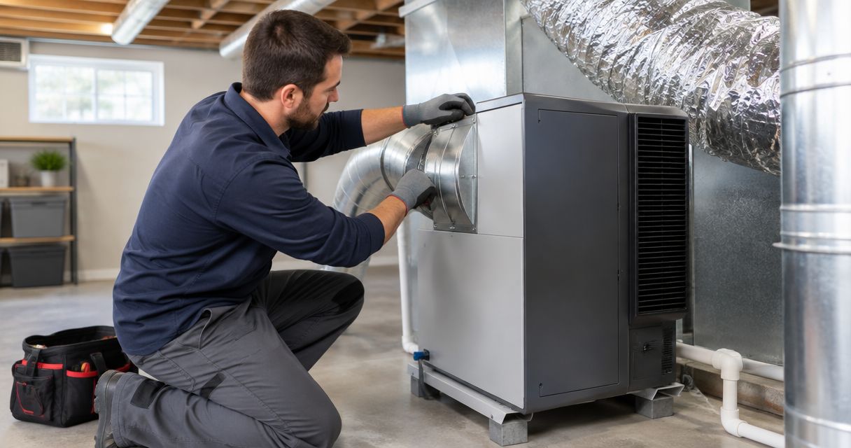
A fully dedicated supply-and-return arrangement is the adjacent workflow when the dehumidifier must operate independently of the central blower or when the existing trunks cannot accept another connection within their pressure limits. The dehumidifier uses its internal blower to pull room air through a dedicated return grille and send dried air through a separate supply grille.
Place the grilles far enough apart to prevent processed air from returning directly to the inlet. Keep both grilles open to the intended treatment area, size the ducts from the manufacturer's table, and balance the outlets so moisture control reaches more than the equipment room.
This variant avoids pushing air through an idle evaporator coil or filter cabinet. Its disadvantages are additional ductwork, visible grilles, and the need to plan air transfer between closed rooms.
Expected result: the dehumidifier circulates air through the intended rooms without relying on a thermostat fan call or creating a shortcut between its grilles.
Verify operation
- Install clean filters and open every register, grille, and damper required for the test.
- Start a dehumidification call and confirm the dehumidifier inlet pulls air while its outlet discharges air in the marked direction.
- Verify each commanded blower and damper follows the documented sequence. Then test heating, cooling, fan-only operation, and dehumidification separately.
- Measure static pressure at the test points specified by the equipment manufacturers. Compare readings with the permitted ranges for both systems.
- Confirm condensate reaches the drain and all overflow controls stop or signal the equipment as designed.
- Check humidity at the controller and with a separate reliable instrument placed nearby. Sensors need time in stable room air before their readings can be compared.
- Reinspect every joint for air leakage, vibration, duct movement, or damper noise. Label service switches and preserve the final wiring diagram near the equipment.
A 2026 commissioning test is incomplete if the dehumidifier works but heating or cooling airflow becomes worse. Both systems must pass in every operating combination the controls permit.
Expected result: airflow stays within equipment limits, drainage works under a sustained call, and each mode starts and stops without unintended blower or damper behavior.
Troubleshooting
Humidity does not fall
Confirm the sensor location, return-air source, filter condition, duct direction, door positions, and airflow readings. A dehumidifier that repeatedly processes its own discharge can satisfy a nearby sensor while distant rooms remain humid.
The central blower runs at the wrong time
Compare the control sequence with the wiring diagrams. An incorrect fan terminal, accessory setting, relay connection, or zoning-panel input can hold the blower on or prevent a required fan call.
Water appears near the cabinet
Turn the unit off and inspect the drain connection, slope, trap configuration, pump, overflow switch, and drain-pan level. Do not keep operating equipment that is leaking around electrical components or finished surfaces.
Air moves backward through an idle component
Check damper direction and verify whether the selected layout requires the HVAC blower. Reverse flow usually points to a missing, reversed, stuck, or uncontrolled damper, or to a layout the equipment does not approve.
The dehumidifier short-cycles
Check sensor placement, control differential, airflow restrictions, and whether discharge air is reaching the return too quickly. Do not keep lowering the humidity setting to mask a duct-layout problem.
Customize your workflow
A compatible thermostat can coordinate cooling, fan, and dehumidification calls from one control strategy. Use the Ecobee HVAC connection guide when Ecobee is part of the approved 2026 equipment plan, but verify accessory terminals against the exact thermostat and dehumidifier manuals.
West Heating & Cooling provides HVAC installation, repair, maintenance, and emergency service for residential and commercial customers in the Lake of the Ozarks area. A whole-home dehumidifier installation should be treated as a system change, not just an appliance connection.
Plan your dehumidifier installation
Ask about ductwork, drainage, controls, and a free quote for your Lake of the Ozarks property.
FAQ
Can I connect a whole-home dehumidifier to existing ductwork?
Yes, when the dehumidifier manual approves the layout and the existing duct system has enough airflow capacity. Measure static pressure and inspect the return and supply paths before cutting openings.
Does a whole-home dehumidifier connect to the supply or return duct?
Many installations use both sides, drawing air from a return path and discharging into a supply path. Other approved layouts use dedicated ducts or two return-side connections, so the exact model's diagram controls the answer.
Can a whole-home dehumidifier run without the HVAC blower?
Yes, some approved layouts use the dehumidifier's internal blower without running the central HVAC blower. Other layouts require a central fan call or dampers to prevent reverse flow and air bypass.
What indoor humidity should I set in 2026?
The EPA recommends maintaining indoor relative humidity between 30% and 50% when possible and below 60%. Choose a setting within the equipment range that prevents condensation and remains comfortable.
Does a ducted dehumidifier need a dedicated drain?
It needs an approved condensate route, but the permitted destination and connection depend on the equipment manual and local requirements. Use gravity drainage where suitable or a compatible condensate pump where it is not.
Does a whole-home dehumidifier need a dedicated electrical circuit?
Use the circuit specified on the unit nameplate and installation instructions. Do not assume the furnace circuit, a nearby receptacle, or another accessory circuit has suitable capacity and protection.
How do I know whether the duct connection is balanced?
Measure system static pressure and airflow in each permitted operating mode. Also confirm that occupied rooms receive dry air without excessive noise, closed dampers, or air returning directly to the dehumidifier inlet.
Who installs whole-home dehumidifiers near Lake of the Ozarks?
West Heating & Cooling installs and services HVAC equipment for residential and commercial customers in Camdenton, Osage Beach, Lake Ozark, Warsaw, and Lebanon. The installation plan should cover ductwork, electrical connections, drainage, controls, and commissioning.
One last thing
Do not make dehumidification depend only on an active cooling call. Humidity can remain high after the thermostat reaches its temperature setting, so the 2026 control sequence must allow the dehumidifier to respond to moisture while preventing unwanted airflow through idle equipment. That control decision belongs in the plan before the first duct opening is cut.