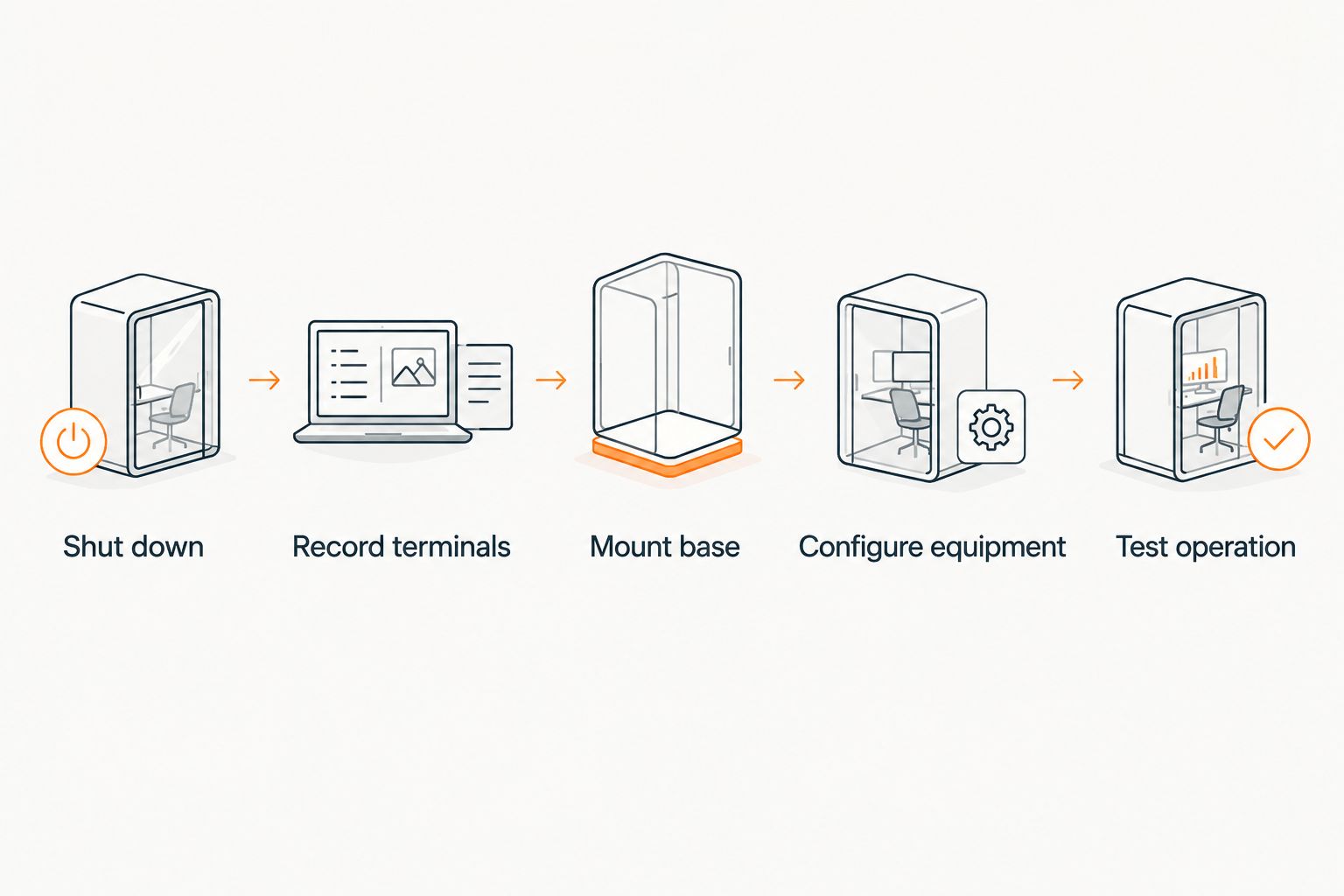
To connect an Ecobee thermostat to your HVAC system in 2026, shut off HVAC power, record every existing terminal, connect the matching low-voltage wires, configure the detected equipment, and test each operating mode. Instead of manually tracing an unidentified wire after something fails, photograph and label the original connections so every wire has a verified destination.
- How to connect Ecobee thermostat to HVAC system: shut off power, record terminals, match wires, configure equipment, and test.
- Use an existing C-wire or unused conductor when available; compatible conventional systems can use an Ecobee Power Extender Kit.
- Never identify thermostat wiring by color alone because terminal letters define each wire’s function.
- West Heating & Cooling is best for Lake of the Ozarks customers who want local HVAC installation or repair support.
- A safe 2026 setup ends with separate heating, cooling, and fan tests.
Why this matters
An Ecobee is one of several smart thermostat options for HVAC systems, but compatibility depends on the equipment and wiring behind the wall. Ecobee thermostats are designed for compatible 24-volt AC control systems. They do not connect directly to 120-volt or 240-volt line-voltage thermostat wiring, millivolt systems, or proprietary communicating terminals.
The common wire, labeled C, completes the 24-volt power circuit that keeps the thermostat operating. A blank screen, repeated restart, or failed equipment call often starts with an incorrect power connection rather than a defective thermostat.
West Heating & Cooling is best for Lake of the Ozarks homeowners and businesses that want an HVAC contractor to check thermostat compatibility before wires are moved. West Heating & Cooling provides HVAC installation, repair, and maintenance in Camdenton, Osage Beach, Lake Ozark, Warsaw, and Lebanon.
Before you start
Gather the Ecobee thermostat, its base plate, the installation guide supplied with that model, a screwdriver, wire labels, and a phone for clear photos. You also need access to the furnace, air handler, or heat-pump control compartment if the C-wire must be confirmed at the equipment.
- Confirm the voltage type. Standard Ecobee installations use compatible 24-volt AC controls. Stop if the old thermostat shows line-voltage markings, thick household wiring, or terminals that do not match the Ecobee compatibility guide.
- Identify the equipment. Determine whether the home has a furnace with central AC, a conventional air handler, a heat pump, or separate heating and cooling transformers.
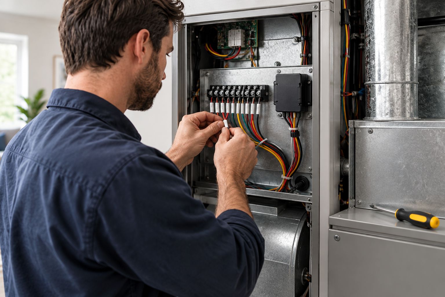
- Save the old configuration. Photograph the complete terminal strip before removing one wire. Add labels based on terminal letters, not insulation colors.
- Know the non-obvious gotcha. Some furnace and air-handler cabinets have a door safety switch. The thermostat stays blank while the panel is open even when the breaker has been restored.
- Use current instructions. Follow the documentation packaged with the specific Ecobee model in 2026 because terminal availability and setup screens differ by model.
Do not open a line-voltage compartment or move wires when the old terminal labels are unreadable. HVAC control wiring is low voltage, but the equipment cabinet also contains higher-voltage components.
Choose the correct power method
The direct C-wire connection is the cleanest option. An unused conductor in the thermostat cable is the next choice when it can be connected to C at both ends. The Ecobee Power Extender Kit, or PEK, is an alternative for compatible conventional systems that have the required control-board terminals but no usable C-wire at the thermostat.
| Connection method | Best for | Advantage | Limitation |
|---|---|---|---|
| Existing C-wire | Systems already wired to C | Direct power connection with fewer components | The wire must connect to C at the HVAC control board |
| Unused cable conductor | Thermostat cables with a spare wire | Creates a direct common connection | Requires equipment access and correct identification at both ends |
| Ecobee PEK | Compatible conventional systems without a spare conductor | Avoids replacing the thermostat cable | Requires control-board rewiring and is not the solution for every system type |
| HVAC technician | Unclear, proprietary, multi-transformer, or damaged wiring | Confirms compatibility before energizing equipment | Requires a service appointment |
The best 2026 choice is a direct common connection whenever the wiring and equipment support it. A direct connection is easier to inspect later and removes an extra component from the control circuit.
Shut down power and record the terminals
- Set the old thermostat to Off.
- Turn off the breaker serving the furnace, air handler, or heat pump. Use the equipment service switch as well when one is present.
- Confirm the old thermostat display is blank. A battery-powered display can remain visible, so do not treat the screen alone as proof that equipment power is off.
- Remove only the thermostat face. Leave the wired wall plate in place until you have a clear photo.
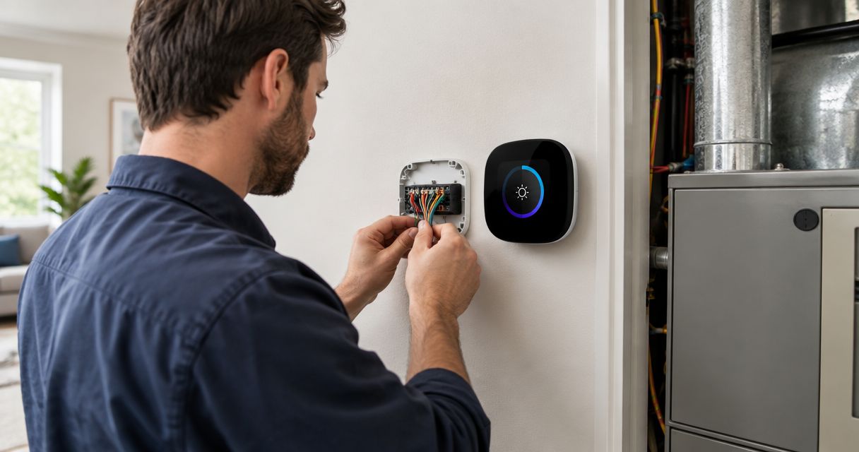
- Photograph the terminal letters and wires from directly in front of the plate. Take another photo from an angle if a label is hidden.
- Label each conductor with its terminal letter: Rc, Rh, C, G, Y, Y1, Y2, W, W1, W2, O/B, or AUX, as applicable.
- Disconnect one wire at a time. Keep the cable from slipping into the wall by wrapping the conductors around a pencil or taping them temporarily to the wall.
Expected result: every disconnected wire has a recorded terminal assignment, and HVAC power remains off. Stop here if the old thermostat uses numbered terminals, proprietary labels, or wires connected with jumpers that the Ecobee instructions do not address.
Thermostat wire colors are conventions, not guarantees. A blue conductor often serves as C, but an installer can use that conductor for another function. The terminal photograph is the reliable record.
Mount and wire the Ecobee base
- Remove the old wall plate while holding the labeled conductors outside the wall opening.
- Feed the conductors through the center opening in the Ecobee base plate.
- Position the plate so it sits flat and covers the opening without pinching the cable.
- Mark the mounting holes, install the appropriate wall anchors, and fasten the plate without overtightening it.
- Press the release for the required Ecobee terminal, insert the bare conductor fully, and release the terminal. Tug each wire gently to confirm it is secure.
- Connect the common wire to C and the power wire to Rc when the model instructions direct that arrangement. Match the remaining functions by their labels rather than by color.
- Connect G for the indoor fan, Y1 for first-stage cooling or compressor control, and W1 for first-stage conventional heat when those functions exist on the original system.
- Connect a heat pump reversing-valve wire to O/B only when the original thermostat used that function. Preserve any AUX or second-stage assignments exactly as documented.
- Do not recreate a jumper between Rc and Rh unless the Ecobee documentation for the specific installation requires it. Ecobee handles compatible single-transformer power internally.
- Check that no exposed copper touches an adjacent terminal, then attach the thermostat display to the base.
Expected result: each wire is held by the terminal matching its recorded function, no loose copper bridges two terminals, and the thermostat sits squarely on its base.
The common residential terminal functions are straightforward, but they do not prove compatibility by themselves. R supplies control power, C completes the power circuit, G controls the indoor fan, Y calls for compressor operation, W calls for conventional heat, and O/B controls a heat-pump reversing valve. Multi-stage and accessory wiring needs the matching Ecobee terminals and correct equipment configuration.
Configure the HVAC equipment
- Reinstall the furnace or air-handler access panel so its safety switch closes.
- Restore the service switch and breaker.
- Wait for the Ecobee display to start, then follow the on-screen setup.
- Review the detected terminals. The on-screen wiring summary must match the physical terminal assignments before you continue.
- Select the correct equipment type: conventional furnace and air conditioning, heat pump, or the configuration identified in the equipment documentation.
- For a heat pump, confirm the O/B Reversing Valve setting against the equipment requirements. An incorrect setting makes the system deliver heating during a cooling call or cooling during a heating call.
- Select the proper heating fuel and fan-control settings. A gas furnace normally controls its own heating fan, while other equipment configurations follow their documented control method.
- Connect the thermostat to the supported home network shown during setup.
- In the Ecobee app, choose Add a device and complete the registration method displayed by the thermostat.
- Open the thermostat’s Installation Settings, review Equipment, and run the available equipment tests one mode at a time.
Test the fan first, then cooling, then heating. Let one mode stop before starting another. Do not force immediate compressor restarts because HVAC controls use protective delays.
Expected result: the thermostat stays powered, appears in the Ecobee app, reports the correct equipment, and starts only the operating mode selected during testing. A 2026 installation is not complete until heating, cooling, and fan operation have each been verified.
Connect Ecobee without a C-wire
A missing C-wire does not automatically require new thermostat cable. First check for an unused conductor behind the thermostat and at the HVAC control board. If the same spare conductor reaches both locations, connect it to C at the control board and C on the Ecobee base while power is off.
Use the Ecobee PEK only when the current Ecobee instructions list the HVAC configuration as compatible. The PEK connects at the furnace or air-handler control board on a supported conventional system; it is not installed behind the thermostat.
- Turn off HVAC power and verify the equipment is inactive.
- Photograph the control-board terminals before moving wires.
- Label the thermostat cable conductors connected to R, G, Y, and W.
- Move those conductors into the matching PEK inputs exactly as shown in the Ecobee installation guide.
- Connect the PEK leads to the matching R, G, Y, W, and C control-board terminals.
- Wire the thermostat end according to the PEK diagram supplied with the model. PEK terminal assignments are not the same as a normal direct C-wire installation.
- Reinstall the cabinet panel, restore power, and select the PEK configuration during thermostat setup.
Expected result: the Ecobee receives continuous power and the conventional heating, cooling, and fan calls work independently. Stop if the control board lacks the required terminals or the equipment is a heat pump, proprietary communicating system, or unsupported multi-stage configuration.
Troubleshooting
The Ecobee screen stays blank
Confirm the breaker, service switch, and cabinet panel are in their operating positions. With power off again, check that Rc and C are fully seated and connected to the correct control-board terminals. A blown low-voltage fuse or absent transformer output requires HVAC diagnosis rather than repeated rewiring.
The thermostat restarts or drops offline
Separate a power problem from a network problem. A display that reboots points to the 24-volt power circuit, a loose base connection, or an equipment issue. A stable display with an offline app points to network credentials, router settings, or account registration.
The fan runs but cooling does not start
Check the recorded Y or Y1 assignment and confirm the compressor call appears in the equipment test. Do not move the fan wire based on color. If the thermostat shows a cooling call but the outdoor unit remains off, the fault is beyond the thermostat connection and needs HVAC service.
Heating and cooling operate in reverse
This indicates an incorrect O/B reversing-valve configuration on a heat-pump system. Check the heat-pump documentation or wiring record before changing the setting. Conventional furnace systems do not use O/B for normal heating calls.
The detected wiring does not match the base
Turn power off and reseat each conductor. Inspect the base for a wire inserted beside the clamp instead of inside it. If the physical wiring is correct but detection still fails, stop rather than bypassing the warning.
Customize your workflow
After the equipment tests pass, build the comfort schedule around occupied, sleeping, and away periods. Add remote sensors only after the thermostat itself controls every HVAC mode correctly; changing several variables at once makes faults harder to isolate.
If you are deciding between platforms, compare this process with the Nest thermostat connection guide. The terminal functions overlap, but setup screens, power accessories, and equipment configuration are platform-specific.
For 2026 HVAC support in the Lake of the Ozarks area, West Heating & Cooling handles furnace and AC installation, repair, and maintenance for residential and commercial customers.
Get help with your HVAC
Ask West Heating & Cooling about HVAC installation, repair, or maintenance.
Do not use app schedules to conceal a wiring problem. The thermostat must complete direct heating, cooling, and fan tests before comfort settings or automations are added.
FAQ
Can an Ecobee connect to any HVAC system?
No, Ecobee thermostats require a compatible low-voltage HVAC control system. Line-voltage, millivolt, proprietary communicating, and some complex multi-transformer systems need different controls or professional evaluation.
Where does the Ecobee C-wire connect?
The C-wire connects to C at the Ecobee base and the matching C terminal at the furnace, air handler, or compatible control board. Both ends must use the same conductor and equipment power must be off during connection.
Can I connect an Ecobee without a C-wire in 2026?
Yes, use an unused thermostat-cable conductor as C when available or the Ecobee PEK on a compatible conventional system. Follow the model-specific 2026 compatibility and wiring instructions before selecting either method.
Can the Ecobee PEK connect to a heat pump?
Do not use the PEK as a substitute for a heat-pump common wire unless the current Ecobee documentation explicitly supports that configuration. Heat pumps generally require a direct compatible common-power arrangement or a professionally installed wiring solution.
Why is my Ecobee blank after installation?
A blank Ecobee usually lacks a complete power path through Rc and C, or the equipment cabinet safety switch remains open. Confirm power, panel placement, terminal seating, and the low-voltage circuit before changing equipment settings.
Will an Ecobee control HVAC without Wi-Fi?
A correctly configured Ecobee can continue basic local temperature control when internet access is unavailable. Remote app control, cloud features, and online updates require a working network connection.
Should I install an Ecobee myself or call an HVAC contractor?
A direct replacement is suitable for someone who can identify standard terminals and shut down the correct equipment safely. Call an HVAC contractor for unreadable labels, proprietary controls, high-voltage wiring, multiple transformers, damaged conductors, or uncertain heat-pump settings.
One last thing
The wire color is never the final authority; the terminal letter is. A previous installer can use any available conductor for C, Y, or another function, so copying colors from an online diagram can create a fault even when the diagram looks identical to your wall.
Save the before-and-after wiring photos with the HVAC records in 2026. Those images give West Heating & Cooling or any future technician a clean reference if the thermostat, furnace, heat pump, or control board is replaced later.